
Kirchhoff’s law
He has two rules.
1. Junction rule or Kirchhoff’s current law (KCL)
According to this rule, the value of the current coming at a junction is equal to the value of the current going out.
The algebraic sum of the currents meeting at a junction is zero
Σi = 0
or,
(i₁+i₂+i₃) – (i₄+i₅) = 0
(i₁+i₂+i₃) = (i₄+i₅)
Kirchhoff’s 1st law expresses the conservation of charge, it is also called Kirchhoff’s current law.
2. Second law or loop rule
According to this rule,
The algebraic sum of potential drops in a closed circuit is equal to zero.
Σi = 0
Proof
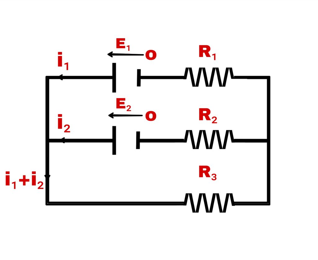
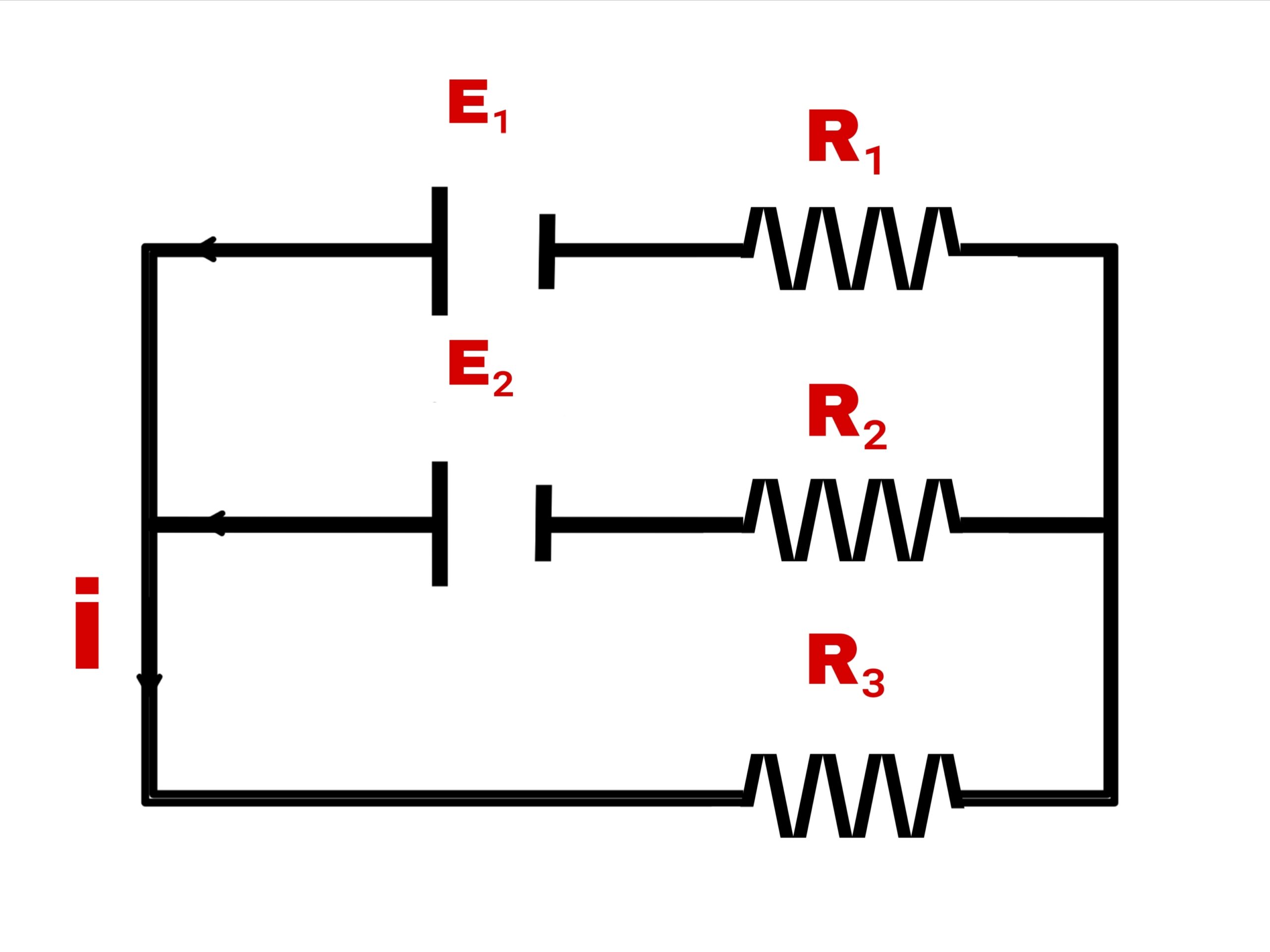
Consider two cells with electromotive force E₁ v E₂ and three resistances R₁, R₂ and R₃ respectively. If the current flowing in R₁ and R₂ is i₁ and i₂ respectively, then according to Kirchhoff’s first law, the current flowing in R₃ is i₁ + i₂
Hence, according to Kirchhoff’s second law,
For closed loop 1,
i₁.R₁+ E₁-i₂.R₂-E₂ =0
i₁.R₁-i₂.R₂+ E₁-E₂=0
For closed loop 2,
E₂ +i₂.R₂+(i₁+i₂).R₃= 0
Note – Kirchhoff’s 2nd law based on the principle of conservation of energy.
Wheatstone bridge
Principle
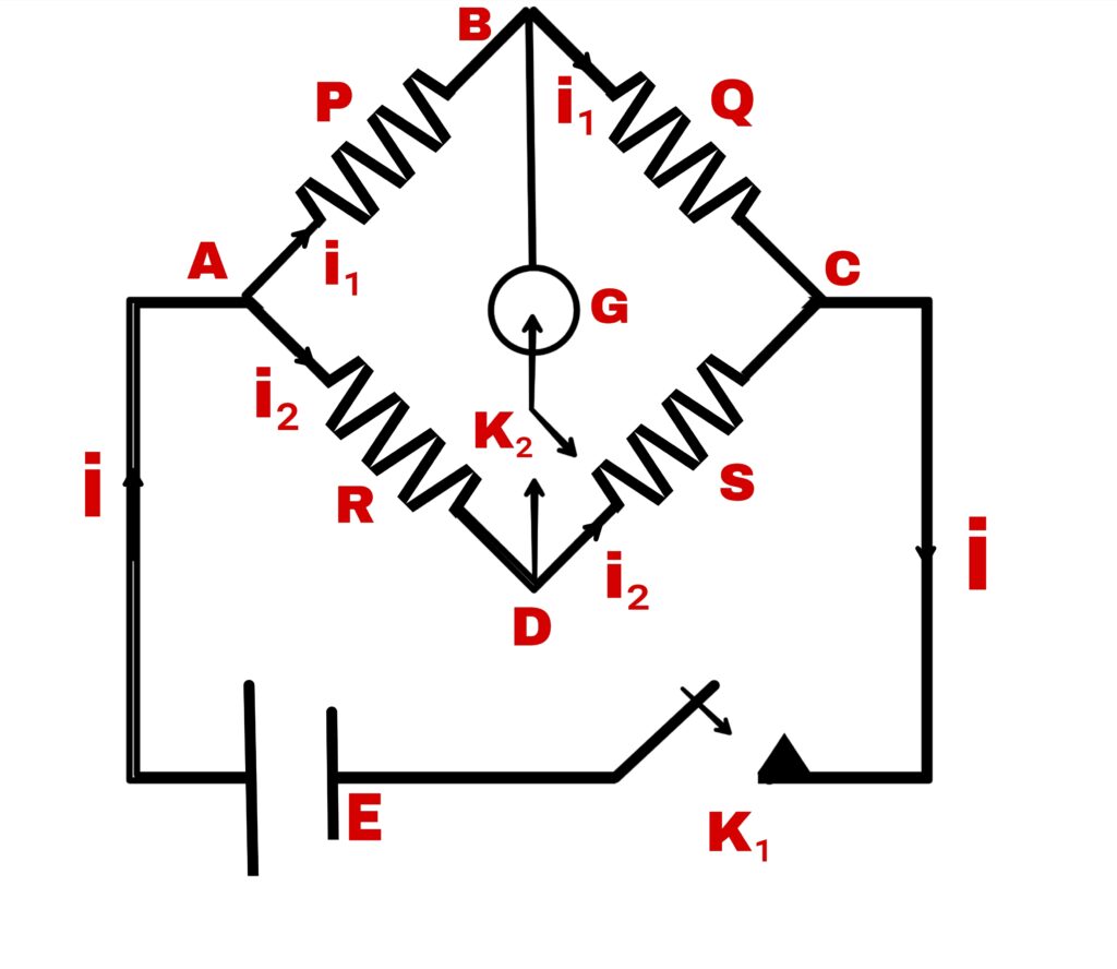
According to this principle,
If four resistances are connected in series and represented by the four sides of a parallelogram and one diagonal of the quadrilateral is connected to the galvanometer and the other diagonal to the electric cell, if there is no declination in the galvanometer G, then,
P/Q=R/S
Proof
Working
Suppose four resistances P, QR and S are connected as four arms of the quadrilateral ABCD. The galvanometer is connected on one side b/w points B & D and the electric cell is connected b/w A & C. There are two keys K₁ and K₂. Current i is passed through the electric cell E.
At point A, the current is divide into two parts, the one part i₁ flows in side AB and the other part i₂ flows in the side AD.
The resistance PQRS is adjusted in such a way that no the current flows in the galvanometer G on pressing the key K₂.
In this case, the current in the arm BC will be i₁, & the current in the arm DC will be i₂
Kirchhoff’s second law for closed loop ABDA
i₁p – i₂R = 0
i₁p = i₂R ———-(1)
For closed loop BCDB
i₁Q – i₂S =0
i₁Q = i₂S ———-(2)
Equation (½)
(i₁p/i₁Q) = (i₂R/i₂S)
P/Q = R/S
Meter bridge
Working and principle
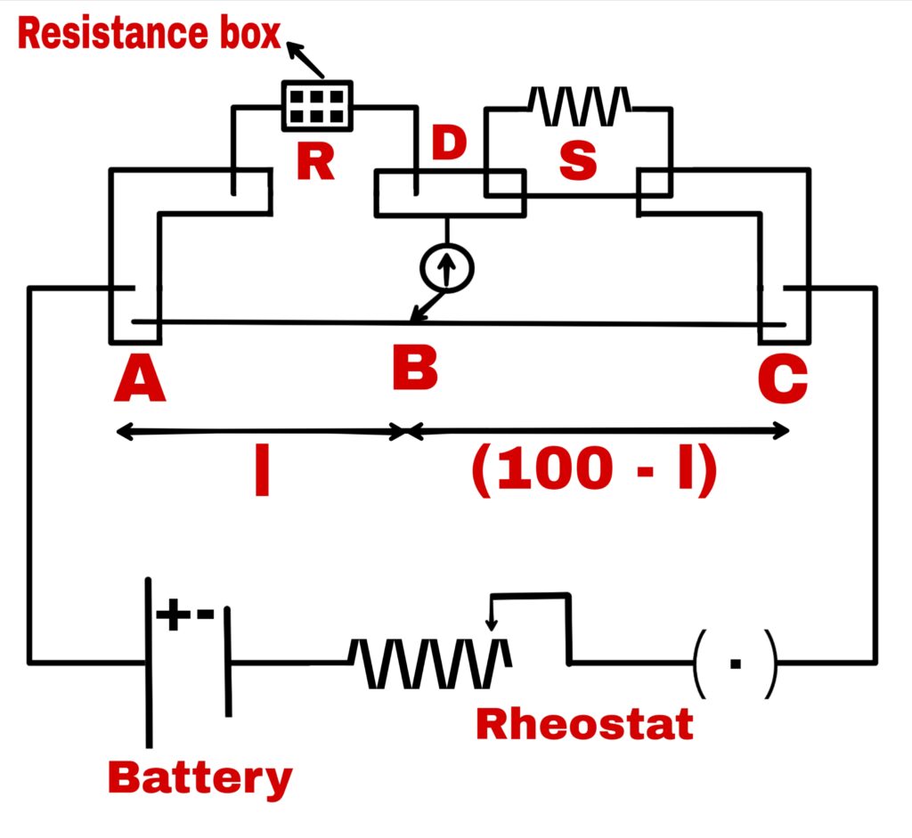
The meter bridge works on the principle of Wheatstone bridge.
The meter bridge has a 1 meter long wire of manganin or constantan which is tightened between AC with the help of meter scale on a wooden base.
The wire whose resistance S is to be the found is placed in the space b/w points C and D and a resistance box is placed in the space b/w points A and D.
A cell current controller and key K are connected b/w points A and C. When the sliding key touches the bridge wire AC at a point B, the wire is divide into two parts. These two parts AB & BC act as the resistance P and Q of Wheatstone bridge.
In case of zero neutral position,
Let the resistance of wire AB = P
The length of wire BC = Q
Hence,
From the principle of Wheatstone bridge,
P/Q = R/S
Hence, the resistance of AB
P = ρ.l/a
Where,
P = specific resistance of the wire
a = wire cross section area
Thus, the resistance of wire BC
Q = ρ.(100-l)/a
l/(100-l) = R/S
S = [(100-l)/l].R
Potentiometer
By this, the electric potential difference between two points is measured accurately.
Question –
What is potentiometer?
Explain its principle by drawing a diagram.
Why is it called ideal voltmeter?
How can its sensitivity be increased?
Solution –
Principle –
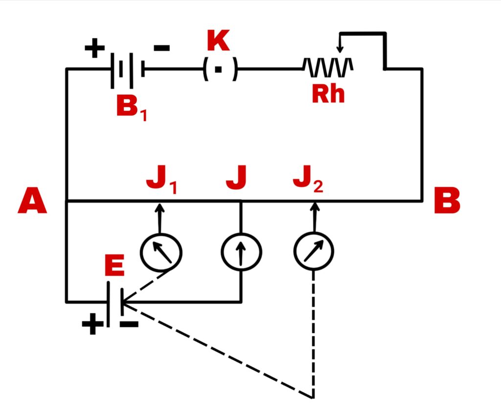
It has a long and uniform diameter metal resistance wire AB whose A is directly connected to the positive pole of an accumulator battery and the negative pole of the battery is connected point B through a rheostat.
Current in the wire AB is reduced or increased by the rheostat. E is a battery cell whose the electromotive force is determined with the help of potentiometer.
Electric current from the battery flows from A to B along the wire. Hence the electric potential keeps falling at every point of the wire from A to B.
The potential fall per unit length of wire is called potential gradient and it is represented by K. If the jockey wire is touched at such a point J₁ that the potential difference between A and J₁ is less than the cell electromotive force E, then the current of battery B₁ will flow into the galvanometer through the AEJ₁ path but the current of the cell will flow into the galvanometer through the AJ₁E path.
Since the electromotive force of the cell is more than the potential difference b/w A and J₁ generated due to the battery.
Hence the needle of galvanometer will deflect towards one the side. On the contrary, if the needle is touched at such a point j₂ of the wire such that the potential difference between A and j₂ is more than the electromotive force of the cell, then the current of battery B₁ will be affected.
So in this condition a resultant current will flow in the galvanometer in the direction AEJ₂ and the galvanometer needle will deflect in opposite direction from before.
If there is a point J b/w J₁ and j₂ at which there is no declination in the galvanometer on touching the needle, then the point J is said to be of zero deflection. In this condition the potential difference between points A and J will be equal to the electromotive force of the cell.
If the current flowing in wire A to B is i and ρ´ is the resistance of isolated length of the wire, then potential difference across wire of length l,
V = electric current × resistance
V = i × lρ´
V = K.l
In the case of zero deflection, the potential difference V will be equal to the electromotive force E of the cell.
E = K.l
Electric cell
Electric cell is a device which controls the flow of charge in the circuit by converting chemical energy into electrical energy. It has two metal rods which are called electrodes or plates. The liquid in which it is immersed is called electrolyte.
Electromotive force of the cell
The electromotive force of the cell is represented by E. If the energy given or the work done by the cell in flowing q coulomb charge in a circuit is W joule, then the electromotive force of the cell
E = W/q
If,
q = 1c
T,hen
E = W
Therefore,
The work done by the cell in flowing a unit charge in the entire circuit is called the electromotive force of the cell.
Terminal potential difference
Suppose the electromotive force of a cell in a pair of electric circuit is E and the energy given out by the cell when q charge flows in the circuit is W.
Then,
E = W/q
If the charge flowing in all the parts of the circuit is q and the energies spent in different parts of the circuit are W1, W2, —– W3 respectively,
Then the energy given out by the cell is
W = W1+W2+W3+——-
Therefore, the electromotive force of the cell is
E = W/qE =( W1+W2+W3+——-)/q
E =W1/q+W2/q+W3/q+——-
E = V1+V2+V3+——
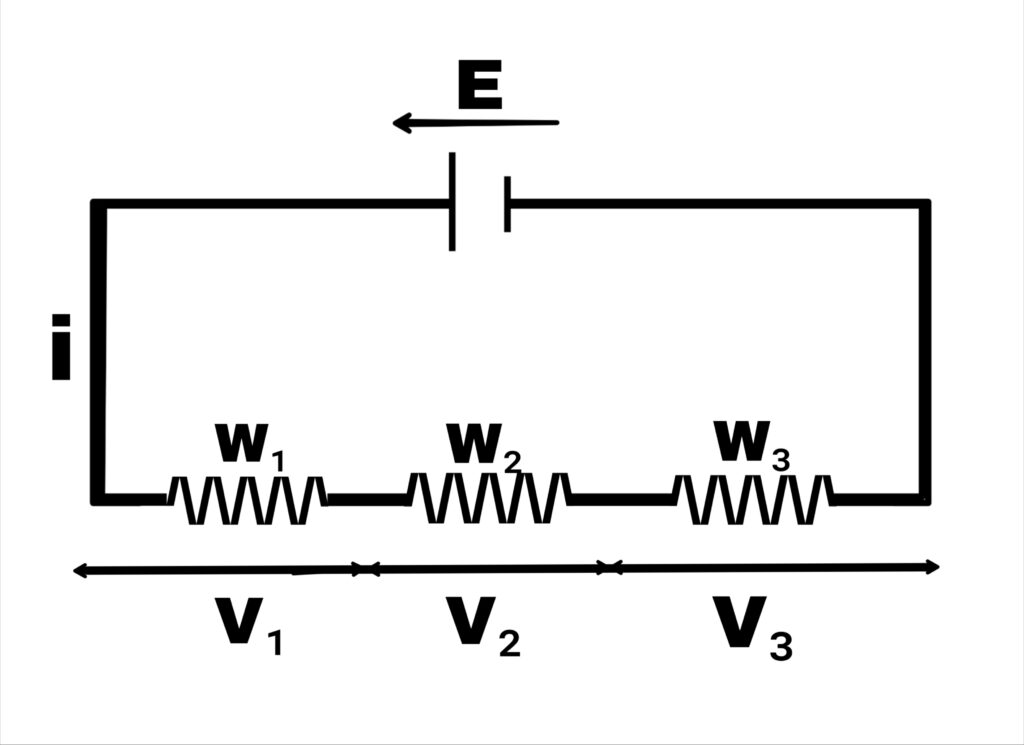
Where V1, V2, and V3 are the terminal potential differences of different parts.
“The work done in passing a unit charge between two points of a circuit is called as the terminal potential difference between those points.”
Internal resistance of a cell
The internal resistance of a cell is represented by r and is defined as follows.
“The obstruction caused by the solution in the flow of electric current between the two plates of a cell is called the internal resistance of the cell.”
The internal resistance of a cell depends on the following things.
1. It is directly proportional to the distance between the two plates of the cell.
2. It is inversely proportional to the area of the plates immersed in the solution.
3. It increases on increasing the concentration of the electrolyte.
4. It depends on the nature of the electrolyte and the material of the plates.
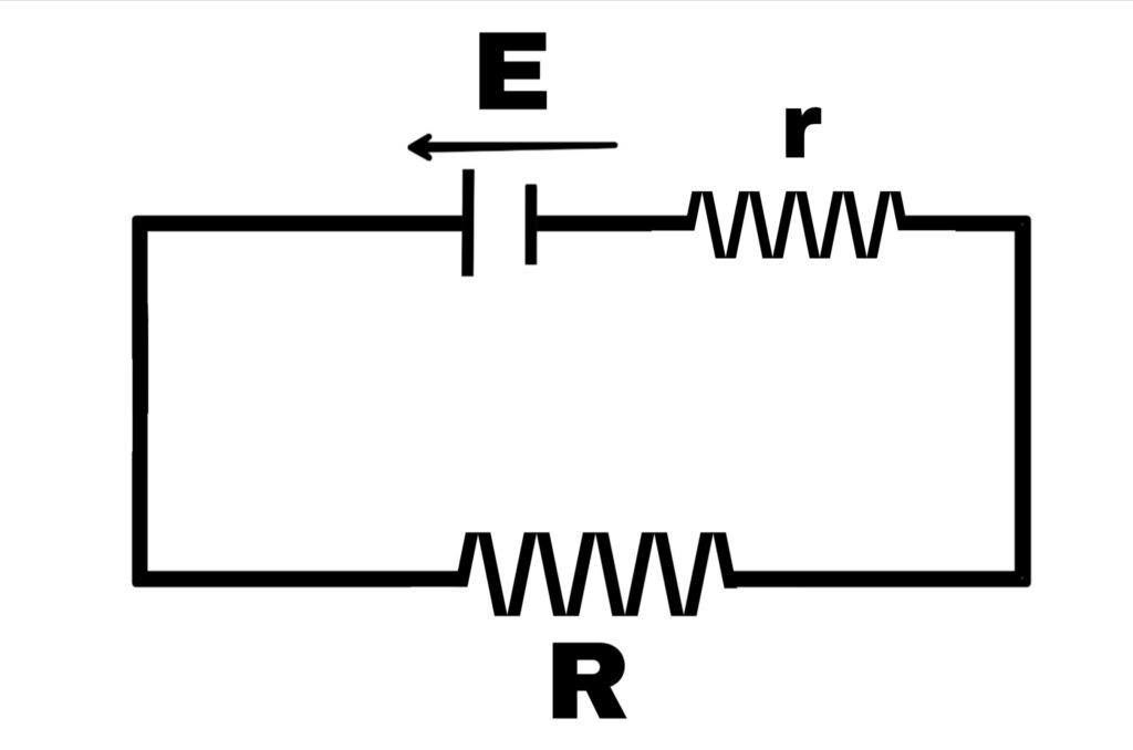
Terminal potential difference of a cell (v) Relation between electromotive force and internal resistance
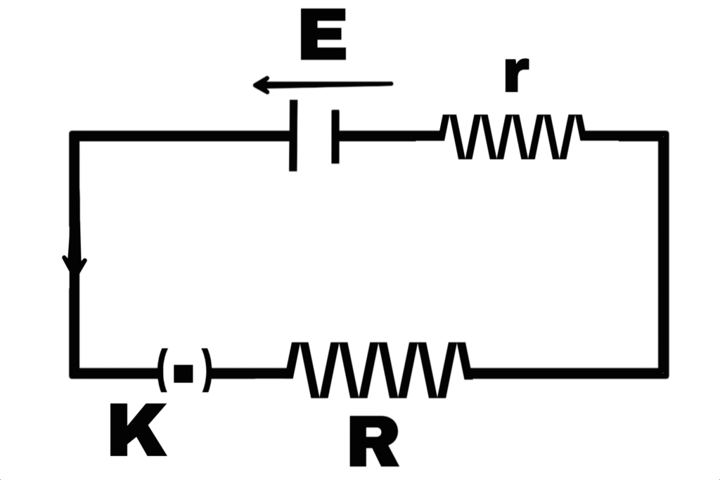
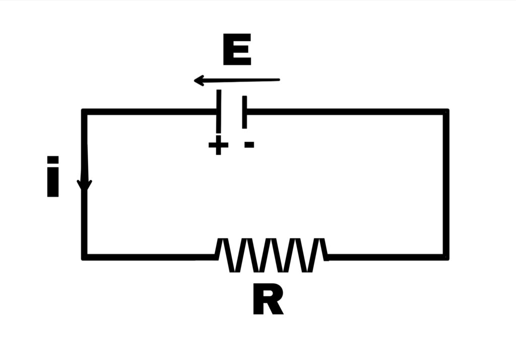
Suppose an electric cell whose electromotive force is E and internal resistance is r. It is connected to external resistance R through a key. If the electric current i flows in the circuit for time t, then the work done by the electric cell
W = E.q
W = E.i.t ————(1)
The work done by the cell will be equal to the work done outside the electric cell and the work done inside the electric cell.
Hence,
W = Wint + Wext —–(2)
If the potential difference between the outer ends is v, then
Wext = V.i.t
Then the current flows in the circuit for time t. Hence the work done by the cell in the internal resistance during the time t when current i flows is
Wint = i².r.t
From equation (2)
W = V.i.t + i².r.t
From equation (1)
E.i.t = V.i.t + i².r.t
E.i.t = i.t(V + i.r)
E = V +i.ri
r = E-V
r = (E-V)/i
V = E – ir
If,
i = 0
V = E
i.e.,current cannot be taken from the electric cell.
Or, if the cell is on open circuit then the terminal potential difference between the plots of the electric cell is equal to the electromotive force of the cell. When there is electric current i in the circuit, then the potential difference between the ends of the resistance r is
V = i.r
Therefore,
Internal resistance of the cell in this situation
r = E.V/i
r = (E-V)/(V/R)
r = R [(E-V)/V]
r = R (E/V – 1)
Value of current in the circuit
E=V+i.r
E = i(R + r)
i = E/(R + r)
Series and parallel circuit
1. Series circuit
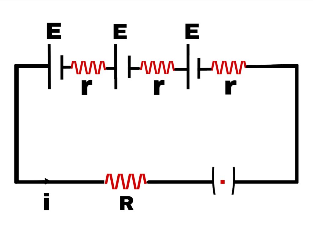
In this type of combination, the negative pole of one cell and the positive pole of the other, the negative pole of the second and the positive pole of the third, the negative pole of the fourth and so on, all the cells are connected.
Suppose n cells are connected in series and the electromotive force of each cell is E and the internal resistance is r. In this case, all the cells are connected to an external R.
So the resultant electromotive force of all the cells = n.E
Total internal resistance = n.r
The total resistance of the circuit = (nr+R)
So the current flowing in the circuit is
i = n.E/(nr+R)
Case 1 –
If n.r << R, then in this case the current in the circuit is
i = n.E/R
In this case,
When the total internal resistance of the cells is much less than the external resistance, then the current generated by the cells will be n times the current flowing in one cell.
Case 2 –
If n.r >> R
i = n.E/n.r
i = E/r
In this case,
If the total internal resistance of all cells is much more than the external resistance, then the current flowing through n cells will be equal to the current flowing through one cell.
2. Parallel circuit
In this type of series, the positive poles of all cells are connected to one point and the negative poles to the other point.
Suppose n cells are connected in normal series, each of which has an electromotive force E and internal resistance r and the external resistance of this battery of n cells is R. The cells are connected in parallel series.
So the electromotive force of the entire battery will be E. If the internal resistance of all the cells is R₁, then,
1/R₁ = 1/r + 1/r +——– upto n terms
1/R₁ = n/r
R₁ = r/n
Hence the total resistance of the circuit will be (r/n+R).
Hence the current flowing in the external circuit
i = E/(r/n+R)
i = n.E/(r + n.R)
Case 1 –
If r <<R
In this case the current flowing in the cell
i = n.E/n.R
i = E/R
That is, the electric current of the total circuit will be equal to the electric current obtained from one cell.
Thus there will be no benefit in connecting cells of low internal resistance in parallel.
Case 2 –
If r>>R
That is,
If the internal resistance of the cells is very large compared to the external resistance, then the current in the circuit
i = n.E/r
Therefore,
When the internal resistance of the cells is very large compared to the external resistance, then they should be connected in parallel.
Case 3 –
If the electromotive force and internal resistance of the cells connected in parallel are different, then the value of the current obtained in any external circuit from these cells is found from Kirchhoff’s law.
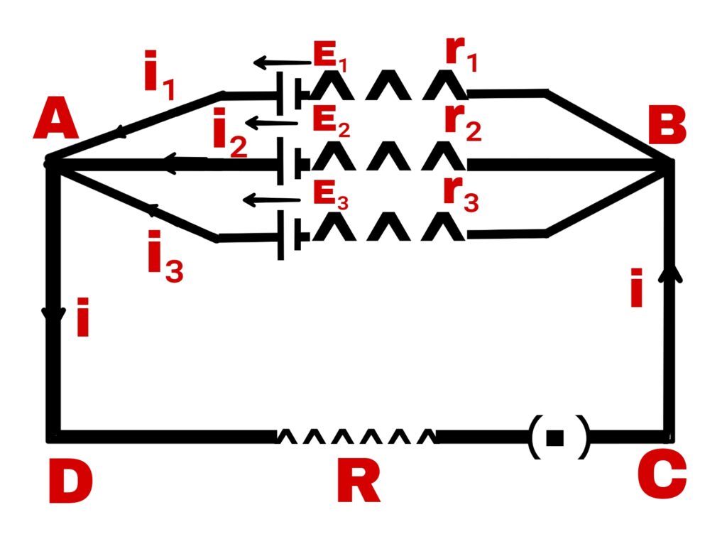
Suppose three cells are connected in parallel whose electromotive force is E₁, E₂ and E₃ and internal resistance is r₁, r₂ and r₃ respectively. If the current generated by these cells is i₁, i₂ and i₃ respectively, then
From K.C.L,
i = i₁ + i₂ + i₃ ———(1)
From K.V.L,
For closed pass ADCBE₁A
i.R + i₁r₁ = E₁
i₁ = (E₁- iR)/r₁
For closed pass ADCBE₂A
i₂.r₂ +iR = E₂
i₂ = (E₂- iR)/r₂
Similarly, for closed pass ADCBE₃A
i₃ = (E₃- iR)/r₃
Putting the values of i₁, i₂, and i₃ in equation (1)
i = (E₁- iR)/r₁ + (E₂- iR)/r₂ + (E₃- iR)/r₃
i = E₁/r₁ + E₂/r₂ + E₃/r₃ -iR[ 1/r₁+1/r₂+1/r₃ ]
i + iR[1/r₁+1/r₂+1/r₃ ] = E₁/r₁ + E₂/r₂ + E₃/r₃
i[1+R(1/r₁+1/r₂+1/r₃)] = E₁/r₁ + E₂/r₂ + E₃/r₃
i = [E₁/r₁ + E₂/r₂ + E₃/r₃]/[1+R(1/r₁+1/r₂+1/r₃)]
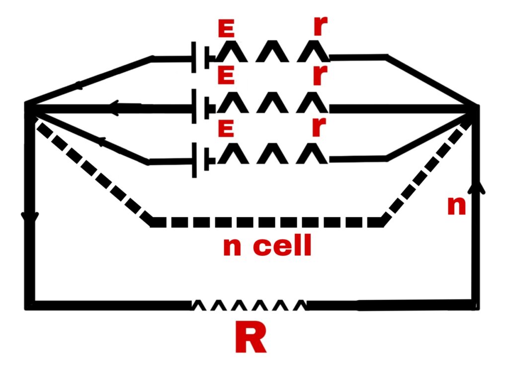
Mixed order circuit or combination circuit
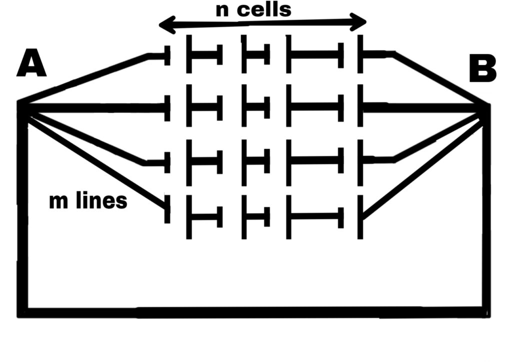
In this type of order some cells are connected in series and all such series are connected in parallel.
Suppose n cells are connected in each row of the series.
Hence, the electric carrier of n cells = n.E
All the series are connected in parallel.
Hence, the electromotive force of the whole battery = n.E
Similarly, the total internal resistance of n cells in a series = n.r
Hence, the total internal resistance of the whole battery
1/R₁ = 1/nr + 1/nr + 1/nr +——— up to m terms
1/R₁ = m/nr
R₁ = nr/m
Hence, the total resistance of the circuit
= (nr/m + R)
Hence, the current flowing in the external circuit
i = n.E/(nr/m + R)
i = m.n.E/n.r + mR
For the value of i to be maximum, the value of (n.r + mR) should be minimum.
n.r + mR = [(√n.r)-(√m.R)]² + 2√m.n.r.R
For (n.r + mR) to be minimum, the value of [(√n.r)-(√m.R)]² should be minimum.
When,
[(√n.r)-(√m.R)]² = 0
Or,
√n.r – √m.R = 0
√n.r = √m.R
n.r = m.R
R = n.r/m
But (n.r/m) is the total internal resistance of the battery.
HenceIn mixed order, the value of current in the external circuit will be maximum when the total internal resistance of the battery is equal to the external resistance.
Hence,
The maximum current flowing in the external circuit is,
i max. = n.E/(nr/m + R)
i max. = n.E/R+R
i max. = n.E/2R
[…] bridge principle What is Kirchhoff’s Law Specific resistance or resistivity Derivation of ohm’s law Electrical current and […]
[…] and parallel circuits wheatstone bridge principle What is Kirchhoff’s Law Specific resistance or resistivity Derivation of ohm’s […]